| Drawlytic automated workflow | Manual drafting workflow | |
|---|---|---|
| Time per part | About a minute, including orientation | 30 minutes to several hours of drafting |
| Who can do it | Anyone with a browser — no CAD seat needed | A trained drafter with a CAD license |
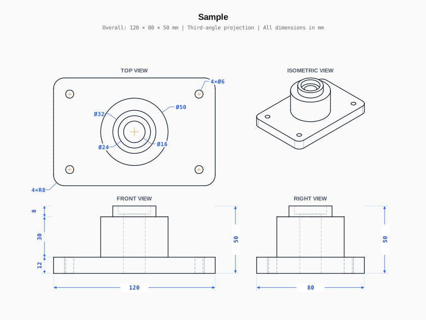
| View projection | Automatic — front/top/right + isometric with hidden-line removal | Manual view placement and alignment |
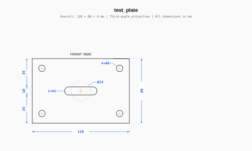
| Dimensioning | Automatic: n×Ø hole groups, radii, angles, overalls, thickness chains | Placed one by one by hand |
| Consistency | Deterministic — same model, same drawing, every time | Varies by drafter and by day |
| Outputs | PDF sheets (A4–A1 + Letter), SVG, projection DXF, 1:1 cut DXF, STL — in one run | Each export prepared separately |
| Design changes | Re-upload the new STEP; a fresh package in a minute | Rework the drawing views and dimensions |
| Tolerances & GD&T | Not generated — add manually where needed | Fully in the drafter's hands |
What "automated" actually means here
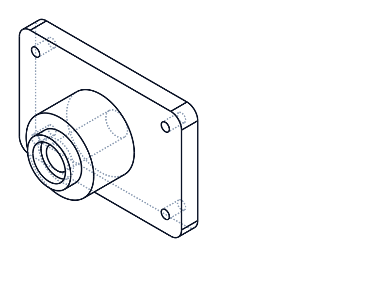
A generic technical drawing — whether drafted in SolidWorks, AutoCAD or on a board — is produced by a person making one decision at a time: which views to place, where to put each dimension, which edges are hidden. Drawlytic automates the mechanical part of that process with the same underlying mathematics CAD systems use. The exact solid from your STEP file is loaded into the OpenCascade geometry kernel; front, top and right views plus an isometric are projected with hidden-line removal; holes, fillets, chamfers and overall extents are detected on the geometry and dimensioned with counted callouts like 4×Ø8 — labels placed with collision avoidance so the sheet stays readable.
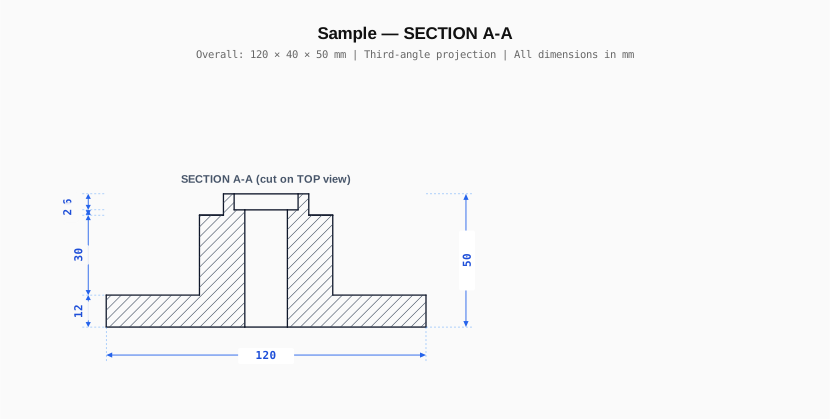
The result follows the conventions a shop expects: third-angle projection, solid visible edges and dashed hidden edges, millimetre units, a framed sheet with a filled title block, and section views hatched at 45° when you cut one. Because it is computed rather than drawn, it is also repeatable — a design revision means re-uploading the new STEP and getting a fresh, consistent package in about a minute, instead of reworking sheets by hand.
What stays human: choosing the orientation that shows the part best (you do this in a 3D preview before generation), adding the specific measurements your inspection plan needs (free, unlimited, with point-to-point and angle tools), and anything beyond geometry — tolerances, GD&T, surface finishes. Automation here replaces the tedious 80%, not the engineering judgment.
Frequently asked
Is an automated technical drawing accurate enough for manufacturing?
Yes — Drawlytic measures every dimension on the exact B-rep geometry in your STEP file, so the numbers match what your CAD system reports. Views are projected with true hidden-line removal, not traced from a render.
What does the automated workflow skip that manual drafting includes?
Judgment calls beyond geometry: tolerances, GD&T callouts, surface finish symbols and weld symbols are not generated automatically. You can add extra measurements free with Measure & adjust; specialized callouts still belong to a human.
How long does an automated drawing take?
Seconds for a typical part once the engine is warm (up to a minute extra after a quiet period). A 20-part assembly generates every part's drawing package in a couple of minutes.
Can I still control how the part is drawn?
Yes — before generation you orient every part in a 3D preview (what 'front' means is your call), and afterwards you can add dimensions, move labels, change paper scale and cut cross sections, free and unlimited.
What do I need to start?
A STEP file (.step/.stp) exported from any CAD system — SolidWorks, Fusion 360, Inventor, CATIA, Onshape, FreeCAD — or a 2D DXF. your first 3 drawings are free, no credit card.
Related guides
See it on your own part
Upload a STEP file and compare the automated drawing with what a drafting session would have produced.
Generate a drawing free →