Help center
The complete Drawlytic user guide
Everything from your first upload to advanced cross sections — written for someone who has never used the software before. Looking for a quick answer instead? Search the FAQ →
1. What is Drawlytic?
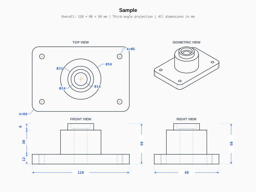
Drawlytic turns 3D CAD models (STEP files) and flat 2D CAD files (DXF) into production-ready technical drawings: front, top and right orthographic views plus an isometric view, projected with true hidden-line removal on the OpenCascade CAD kernel. Hole diameters (Ø), radii (R), angles and overall dimensions are placed automatically, and everything is delivered as vector SVG, DXF, STL and framed PDF sheets with a title block.
2. Creating your account
- 1Click Sign up in the top-right corner and enter your e-mail and a password (at least 6 characters).
- 2Open the activation e-mail we send you and click the link — it is valid for 24 hours. You cannot log in before activating.
- 3Log in. The counter in the top bar shows your remaining drawings (3 free per month on the free plan).
3. Uploading a model
On the home page, drag your file into the upload box (or click it to browse). Supported inputs:
- .step / .stp — 3D models (STEP AP203, AP214, AP242) from any CAD software: SolidWorks, Fusion 360, FreeCAD, Inventor, CATIA, Onshape…
- .dxf — flat 2D geometry (see section 8).
- .dwg — converted to DXF automatically on the server (AutoCAD R13 through 2018 formats). If a particular file can't be converted, the app tells you and you can export it as DXF instead.
Maximum file size is 25 MB. Assemblies are supported: each solid body becomes its own part with its own complete drawing package (up to 30 parts, largest first) — plus an assembly drawing of the whole model.
4. Orienting & naming parts (3D preview)
After a STEP upload, each part is shown as an interactive 3D preview so you decide what "front" means before anything is drawn.
- 1Rotate each part with the mouse until it faces the way you want it drawn.
- 2Use the quick-orientation buttons to snap to standard directions if you don't need a custom pose.
- 3Give the project and each part a name — these appear in the drawing header and the PDF title block.
- 4Click Generate drawings. This consumes one drawing from your monthly quota (or one credit).
5. Generating the technical drawing
What happens while the progress bar runs:
- 1The engine loads your model and applies your chosen orientation.
- 2Front, top and right views are projected with hidden-line removal — visible edges solid, hidden edges dashed.
- 3Features are detected and dimensioned automatically: hole groups (e.g. 4×Ø8), fillet radii, chamfer/taper angles, overall width / height / depth.
- 4The drawing, exports and PDF sheets for every paper size are rendered and saved to My Projects.
The first run after a quiet period can take up to a minute extra — the drawing engine boots on demand (the status text tells you when this is happening). Typical parts finish in seconds; complex assemblies can take a minute or two.
6. Measure & adjust
Open a finished drawing and click 📐 Measure & adjust. This is free — it never consumes quota — and you can apply it as many times as you like.
Adding your own measurements
- 1Pick the part (if an assembly) and a view tab: FRONT / TOP / RIGHT.
- 2Edge mode — click any edge or circle to dimension it (clicking again removes it). Circles get Ø automatically.
- 3Point → point mode — click two corner points to measure the distance between them.
- 4∠ Angle mode — click the corner (vertex) first, then one point on each edge.
- 5Drag any measurement to move it; use A− / A+ on its chip to change its text size.
- 6Choose a PDF scale (Fit page, 1:1, 1:2, 1:4, 1:8) and click Apply to drawing & PDF.
The amber automatic dimensions
Amber items are dimensions the drawing already shows automatically — displayed so you don't duplicate them. You can drag their labels to reposition them and resize their text with the amber A− / A+ chips; the ↺ button resets one to its automatic position.
7. Cross Section Drawing
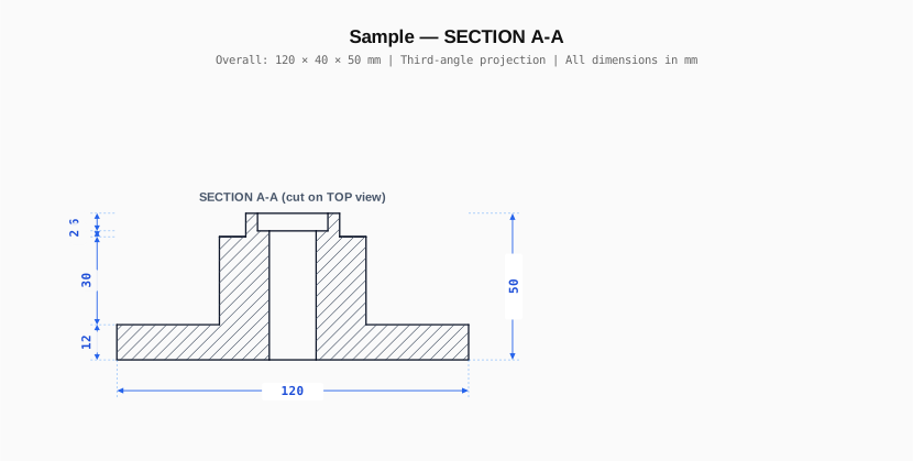
- 1On a finished drawing, click ✂ Cross Section Drawing.
- 2Pick the part and the view you want to cut on (FRONT / TOP / RIGHT).
- 3Click two points to draw the cutting line A–A. The line snaps to perfectly horizontal or vertical — no freehand angles.
- 4The arrows show the viewing direction: material in front of the arrows is removed. Click ⇄ Flip viewing side to look from the other side.
- 5Click Generate cross section drawing. It's free — cross sections never consume your quota.
- 6The section appears under your main drawing with its own Cross section sheet (PDF) download in every paper size.
The result follows drafting standards: a true section plane, cut faces hatched at 45°, hidden lines omitted, labelled SECTION A-A with the source view noted.
8. 2D DXF drawings
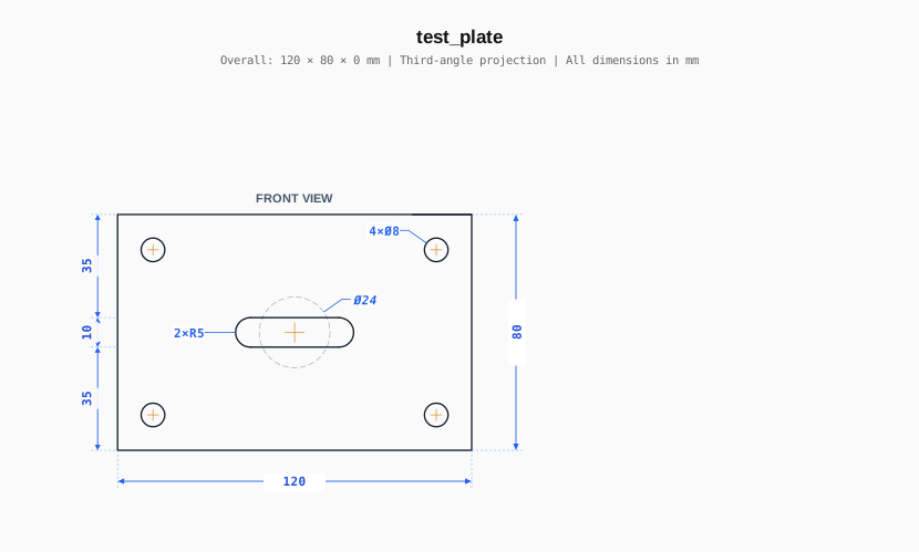
- 1Upload a .dxf file exactly like a STEP file — same upload box.
- 2There is no 3D orientation stage: the drawing generates immediately (this consumes one drawing, like a STEP generation).
- 3Geometry and scale are preserved 1:1. Entities on HIDDEN/dashed linetypes or layers named with "HIDDEN" render as dashed lines.
- 4Holes, slots and radii are grouped and dimensioned automatically.
SAVEAS → DXF) and upload that instead.9. Downloads & export options
Every generated part comes with a full export package:
- Technical drawing (SVG) — crisp vector, opens in any browser or vector editor.
- Drawing sheet (PDF) — the drawing on a framed sheet with title block. Choose A4, A3, A2, A1 or Letter from the dropdown next to the download button. Text is automatically re-laid-out so it prints at a readable size on every paper format.
- Cross section (SVG) + Cross section sheet (PDF) — when you've generated a cross section.
- 2D projection (DXF) — all views on VISIBLE/HIDDEN layers, for CAD.
- Top view DXF — cut contours only at 1:1, ready for laser/CNC.
- Mesh reference (STL) — triangulated model for viewers and 3D printing.
- Download all (ZIP) — one click for the whole package (paid drawings).
Free plan limits: PDF sheets are A4 only and carry a watermark; DXF exports and larger paper sizes are unlocked by Pro or credits — including retroactively on your existing drawings.
All dimensions are in millimetres (noted on every sheet).
10. Plans, credits & billing
- Free — 3 drawings per month, watermarked A4 PDF, no DXF export. Measure & adjust and cross sections are always free and unlimited on drawings you've generated.
- Pro ($19/month) — 100 drawings per month, every paper size, no watermark, DXF exports, ZIP download. Going Pro also unlocks your existing drawings.
- Credit packs (any plan) — pay-as-you-go drawings that carry over month to month, from $0.28 per drawing. On the free plan, each credit buys one full Pro-tier drawing.
- Monthly Pro quota does not roll over; purchased credits do.
- Deleting a project archives it — you can restore it later without being charged again, and deleting never refunds a use.
- Payments are processed by Polar (our merchant of record); invoices and receipts arrive by e-mail, and you can manage or cancel your subscription any time from Account → Manage billing.
11. Troubleshooting & error messages
"Please upload a .step, .stp, .dxf or .dwg file"
The file extension isn't supported. Export your model as STEP (3D) or DXF (2D) from your CAD software and try again.
"No solid bodies were found in this STEP file"
The STEP contains only surfaces or wireframes. Re-export as a solid model (in most CAD tools: make sure the body is a closed solid before exporting).
"You've used all 3 free drawings this month"
The free quota resets on the 1st of each month. Upgrade to Pro or wait for the reset — finished drawings stay accessible either way.
"This drawing was generated before cross sections existed…"
Older drawings aren't linked to their source STEP file. Upload the STEP once more; every drawing from now on supports cross sections.
"DWG conversion failed — please export as DXF"
Most DWG files (AutoCAD R13–2018) convert automatically; a few unusual or damaged ones don't. Save the file as DXF in your CAD package and upload the DXF instead — the result is identical.
Progress seems stuck near 0% with "Starting the engine…"
The drawing engine boots on demand after a quiet period — the first job can take up to a minute before progress moves. If nothing changes for several minutes, refresh the page; your job keeps running server-side and the finished result is saved to My Projects.
The page looks broken or buttons are missing after an update
Do a hard refresh (Ctrl+Shift+R / Cmd+Shift+R) so your browser loads the newest version.
Activation or reset e-mail never arrives
Check your spam folder, then use the resend button on the login screen. Corporate mail servers occasionally delay delivery by a few minutes.
Still stuck? Write to support@drawlytic.com with the project name and roughly when it happened.
12. Tips & best practices
- Orient before you generate — a good front view saves you manual dimensions later.
- Let the amber dims work for you: the drawing already dimensions holes, radii, angles and overall sizes. Add manual measurements only for what's missing, and drag amber labels instead of duplicating them.
- Use 1:1 or 1:2 scale for parts that fit the sheet — machinists love true-scale prints. Use "Fit page" for large parts.
- Cut where the detail is: place cross section lines through hole axes and pockets — that's where a section view adds the most information.
- Name parts properly before generating — names go on every sheet's title block.
- Use the ZIP download to hand a complete package (PDF + DXF + STL) to your manufacturer in one file.
Didn't find what you need?
Try the searchable FAQ — or e-mail us and we'll help directly.